本次实验(一)见博客:【数字电路与系统】【北京航空航天大学】实验:时序逻辑设计——三色灯开关(一)、实验指导书
本次实验(二)见博客:【数字电路与系统】【北京航空航天大学】实验:时序逻辑设计——三色灯开关(二)、需求分析和系统设计
说明:本次实验的代码使用verilog编写,文章中为阅读方便,故采用matlab代码格式。
2.3、功能仿真测试
2.3.1、测试程序设计
//mode_run模块:
因为仿真本来就是理想信号,所以需要去掉debounce模块进行仿真

module test2;

	// Inputs
	reg clk;
	reg rst;
	reg key0;
	reg key1;

	// Outputs
	wire [3:0] led;

	// Instantiate the Unit Under Test (UUT)
	mode_run_1 uut (
		.clk(clk),
		.rst(rst),
		.key0(key0),
		.key1(key1),
		.led(led)
	);

	initial begin
		// Initialize Inputs
		clk = 0;
		rst = 0;
		key0 = 0;
		key1 = 0;

		// Wait 100 ns for global reset to finish
		#100;

		// Add stimulus here

	end
   #10 clk = ~clk;
   #1000 key0 = ~key0;
endmodule
//mode_demo模块:
因为仿真本来就是理想信号,所以需要去掉debounce模块进行仿真
module mode_demo_1_sim;

	// Inputs
	reg clk;
	reg rst;
	reg key_0;
	reg key_1;

	// Outputs
	wire dp;
	wire [6:0] light;
	wire [1:0] com;

	// Instantiate the Unit Under Test (UUT)
	mode_demo_1 uut (
		.clk(clk),
		.rst(rst),
		.key_0(key_0),
		.key_1(key_1),
		.dp(dp),
		.light(light),
		.com(com)
	);

	initial begin
		// Initialize Inputs
		clk = 0;
		rst = 0;
		key_0 = 0;
		key_1 = 0;

		// Wait 100 ns for global reset to finish
		#100;
       rst = 1;
		// Add stimulus here

	end
   always #10 clk = ~clk;
	always #10000 key_0 = ~key_0;
endmodule
//Uart_top模块:
	module uart_top_tb;

	// Inputs
	reg Sys_CLK;
	reg Sys_RST;
	reg [1:0] Key_In;

	// Outputs
	wire Signal_Tx;


	// Instantiate the Unit Under Test (UUT)
	Uart_Top uut (
		.Sys_CLK(Sys_CLK),
		.Sys_RST(Sys_RST),
		.Key_In(Key_In),
		.Signal_Tx(Signal_Tx)
	);

	initial begin
		// Initialize Inputs
		Sys_CLK = 0;
		Sys_RST = 1;
		Key_In = 0;

		// Wait 100 ns for global reset to finish
		#100;
		Sys_RST = 0;
		#100;
		Sys_RST = 1;

		#100000000;
		Key_In = 2'b01;
		#100000000;
		Key_In = 2'b00;

		#100000000;
		Key_In = 2'b01;
		#150000000;
		Key_In = 2'b00;

		#100000000;
		Key_In = 2'b01;
		#200000000;
		Key_In = 2'b10;
		#100000000;
		Key_In = 2'b00;


		// Add stimulus here

	end


always #10 Sys_CLK = ~Sys_CLK;


endmodule
2.3.2、功能仿真过程
//mode_run模块:
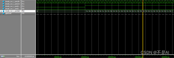
图 2 mode_run仿真
//mode_demo模块:
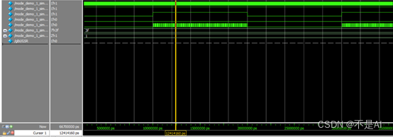
图 3 mode_demo仿真
//Uart_top模块:
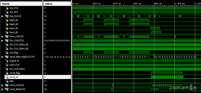
图 4 Uart_top仿真
2.3.2、实验关键结果及其解释
//mode_run模块:
在mode_run仿真过程中,在key0置1过后,状态机进入白光—灭—日光—灭—黄光—灭的循环,仿真结果符合实验需求。
//mode_demo模块:
在mode_demo仿真过程中,在key0置1过后,状态机也进入了白光—灭—日光—灭—黄光—灭的循环,仿真结果符合实验需求。
//Uart_top模块:
在Uart_top模块中,Sw不断变化后,按下Key,将Sw的变化一次发送到Tx显示,仿真符合实验设计要求。
(未完待续)